 Cisco and VMware have collaborated to address new challenges that have arisen from the introduction of bladed server architectures and subsequently of server virtualization. With Cisco VN-Link, you will find a portfolio of networking solutions that can operate directly within the distributed hypervisor layer and offer a feature set and operational model that is familiar and consistent with other Cisco networking products. This approach provides an end-to-end network solution to the new requirements created by server virtualization.
Is it State-of-the-Art or pre-launch advertising? In any case I believe that Cisco’s overview of this new (and at least partially proprietary) hardware-centric approach to Network Virtualization is a must read. It contains a very sound summary of the network challenges in virtualized environments, a recap of VMware’s Distributed Virtual Switch (DVS), Cisco’s Nexus 1000V and a somewhat vague introduction to concepts such as port profile, VN-Link and vEth.
Here is what Cisco’s Whitepaper describes:
The design of modern data center networks is based on a proven layered approach, which has been tested and improved over the past several years in some of the largest data center implementations in the world. The three layers of a data center network are:
• Core layer, the high-speed packet switching backplane for all flows going in and out of the data center
• Aggregation layer, providing important functions such as the integration of network-hosted services: load balancing, intrusion detection, firewalls, SSL offload, network analysis, and more
• Access layer, where the servers physically attach to the network and where the network policies (access control lists [ACLs], quality of service [QoS], VLANs, etc.) are enforced
The access-layer network infrastructure can be implemented with either large, modular switches, typically located at the end of each row, providing connectivity for each of the servers located within that row (the end-of-row model,) or smaller, fixed configuration top-of-rack switches that provide connectivity to one or a few adjacent racks and have uplinks to the aggregation-layer devices (the top-of-rack model.) Bladed server architectures modify the access layer by allowing an optional embedded blade switch to be located within the blade enclosure. Blade switches, which are functionally similar to access-layer switches, are topologically located at the access layer; however, they are often deployed as an additional layer of the network between access-layer switches and computing nodes (blades), thus introducing a fourth layer in the network design.
Effects of Virtualization
Server virtualization modifies both of the previously mentioned assumptions of data center network design by allowing multiple OS images to transparently share the same physical server and I/O devices. As a consequence, it introduces the need to support local switching between different virtual machines within the same server, thus pushing the access layer of the network further away from its original location and invalidating the assumption that each network access port correspond to a single physical server running a single image.
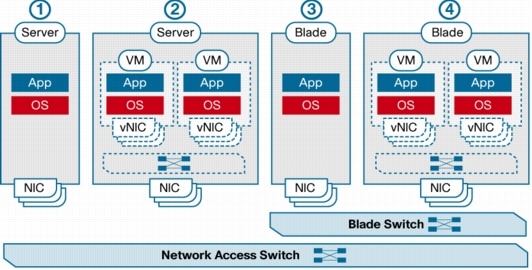
Server virtualization also invalidates a second assumption: the static nature of the relationship between an image and the network. By abstracting hardware from software, virtualization effectively enables OS images to become mobile, which means that a virtual machine can be moved from one physical server to another within the data center or even across multiple data centers. This move can take place within the same access switch or to another access switch in the same or a different data center. The consequences of this new level of mobility on the network are not trivial, and their effects may go beyond just the access layer, as, for example, some of the services deployed in the aggregation layer may need to be modified to support virtual machine mobility. Even in terms of pure Layer 2 switching and connectivity, mobility of virtual machines, implemented by products such as VMware VMotion, poses fairly stringent requirements on the underlying network infrastructure, especially at the access layer. For example, it requires that both the source and destination hosts be part of the same set of Layer 2 domains (VLANs). Therefore, all switch ports of a particular virtualization cluster must be configured uniformly as trunk ports that allow traffic from any of the VLANs used by the cluster’s virtual machines, certainly not a classic network design best practice. Figure 1 provides a visual comparison of the different access layer connectivity options.
Figure 1. Comparison of Access Layer Connectivity Options in (1) Nonvirtualized Rack-Optimized Server, (2) Virtualized Rack-Optimized Server, (3) Nonvirtualized Blade Server, and (4) Virtualized Blade Server

Virtual machine mobility also breaks several other features that have been implemented in the network under the assumption that computing is relatively static and moving a physical server in the data center is not a practical thing to do very often. For example, features such as port security, IEEE 802.1x, and IP source guard that maintain state information based on the physical port cannot be deployed in the current generation of access-layer switches since the virtual machine may move at any point in time. Further, as virtual machines move from one physical server to another, it is also desirable that all the network policies defined in the network for the virtual machine (for example, ACLs) be consistently applied, no matter what the location of the virtual machine in the network.
Hypervisor-Embedded Virtual Switch
The easiest and most straightforward way to network virtual machines is to implement a standalone software switch as part of the hypervisor. This is what VMware did with the virtual switch (vSwitch). Each virtual network interface card (vNIC) logically connects a virtual machine to the vSwitch and allows the virtual machine to send and receive traffic through that interface. If two vNICs attached to the same vSwitch need to communicate with each other, the vSwitch will perform the Layer 2 switching function directly, without any need to send traffic to the physical network.
The primary benefit of the embedded vSwitch approach is its simplicity: each hypervisor includes one or more independent instances of the vSwitch. Unfortunately, this strength becomes a weakness when it comes to deploying several VMware ESX servers in the data center, since each embedded vSwitch represents an independent point of configuration. Another problem with the vSwitch is that it represents a piece of the network that is not managed consistently with the rest of the network infrastructure; in fact, network administrators often do not even have access to the vSwitch. In many practical cases, the vSwitch is an unmanaged network device, certainly not a desirable situation, especially in mission-critical or highly regulated environments, where IT departments rely on network capabilities to help ensure the proper level of compliance and visibility. This approach creates operation inconsistencies in a critical point of the IT infrastructure where the server administrator now has the liability of maintaining and securing a portion of the network without the use of the best practices, diagnostic tools, and management and monitoring available throughout the rest of the infrastructure.
Furthermore, vSwitches do not do anything special to solve the problem of virtual machine mobility; the administrator must manually make sure that the vSwitches on both the originating and target VMware ESX hosts and the upstream physical access-layer ports are consistently configured so that the migration of the virtual machine can take place without breaking network policies or basic connectivity. In a virtualized server environment, in which virtual machine networking is performed through vSwitches, the configuration of physical access-layer ports as trunk ports is an unavoidable requirement if mobility needs to be supported.
To overcome the limitations of the embedded vSwitch, VMware and Cisco jointly developed the concept of a distributed virtual switch (DVS), which essentially decouples the control and data planes of the embedded switch and allows multiple, independent vSwitches (data planes) to be managed by a centralized management system (control plane.) VMware has branded its own implementation of DVS as the vNetwork Distributed Switch, and the control plane component is implemented within VMware vCenter. This approach effectively allows virtual machine administrators to move away from host-level network configuration and manage network connectivity at the VMware ESX cluster level.
Cisco VN-Link
Cisco is using the DVS framework to deliver a portfolio of networking solutions that can operate directly within the distributed hypervisor layer and offer a feature set and operational model that are familiar and consistent with other Cisco networking products. This approach provides an end-to-end network solution to meet the new requirements created by server virtualization. Specifically, it introduces a new set of features and capabilities that enable virtual machine interfaces to be individually identified, configured, monitored, migrated, and diagnosed in a way that is consistent with the current network operation models.
These features are collectively referred to as Cisco Virtual Network Link (VN-Link). The term literally indicates the creation of a logical link between a vNIC on a virtual machine and a Cisco switch enabled for VN-Link. This mapping is the logical equivalent of using a cable to connect a NIC with a network port of an access-layer switch.
Virtual Ethernet Interfaces
A switch enabled for VN-Link operates on the basis of the concept of virtual Ethernet (vEth) interfaces. These virtual interfaces are dynamically provisioned based on network policies stored in the switch as the result of virtual machine provisioning operations by the hypervisor management layer (for example, VMware vCenter.) These virtual interfaces then maintain network configuration attributes, security, and statistics for a given virtual interface across mobility events.
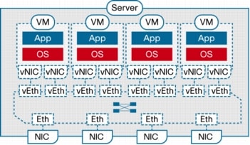
Virtual Ethernet interfaces are the virtual equivalent of physical network access ports. A switch enabled for VN-Link can implement several vEth interfaces per physical port, and it creates a mapping between each vEth interface and the corresponding vNIC on the virtual machine. A very important benefit of vEth interfaces is that they can follow vNICs when virtual machines move from one physical server to another. The movement is performed while maintaining the port configuration and state, including NetFlow, port statistics, and any Switched Port Analyzer (SPAN) session. By virtualizing the network access port with vEth interfaces, VN-Link effectively enables transparent mobility of virtual machines across different physical servers and different physical access-layer switches.
Port Profiles
Port profiles are a collection of interface configuration commands that can be dynamically applied at either physical or virtual interfaces. Any changes to a given port profile are propagated immediately to all ports that have been associated with it. A port profile can define a quite sophisticated collection of attributes such as VLAN, private VLAN (PVLAN), ACL, port security, NetFlow collection, rate limiting, QoS marking, and even remote-port mirroring (through Encapsulated Remote SPAN [ERSPAN]) for advanced, per-virtual machine troubleshooting.
An example of a port profile configuration is shown here:
(config)# port-profile webservers
(config-port-prof)# switchport access vlan 10
(config-port-prof)# ip access-group 500 in
(config-port-prof)# inherit port-profile server
The port profile can then be assigned to a given vEth interface as follows:
(config)# interface veth1
(config-if)# inherit port-profile webservers
Figure 2. Relationship Between Virtual and Physical Network Constructs in a VN-Link Enabled Switch (Cisco Nexus™ 1000V Series Switches)
Port profiles are tightly integrated with the management layer for the virtual machines (for example, VMware vCenter) and enable simplified management of the virtual infrastructure. Port profiles are managed and configured by network administrators. To facilitate integration with the virtual machine management layer, Cisco VN-Link switches can push the catalog of port profiles into virtual machine management solutions such as VMware vCenter, where they are represented as distinct port groups. This integration allows virtual machine administrators to simply choose among a menu of profiles as they create virtual machines. When a virtual machine is powered on or off, its corresponding profiles are used to dynamically configure the vEth in the VN-Link switch.
VN-Link can be implemented in two ways:
• As a Cisco DVS running entirely in software within the hypervisor layer (Cisco Nexus 1000V Series)
• With a new class of devices that support network interface virtualization (NIV) and eliminate the need for software-based switching within hypervisors
Deploying VN-Link in Existing Networks with the Cisco Nexus 1000V Series
With the introduction of the DVS framework, VMware also allowed third-party networking vendors to provide their own implementations of distributed virtual switches by using the vNetwork switch API interfaces. Cisco and VMware collaborated closely on the design of these APIs, and the Cisco Nexus 1000V Series represents the first example of third-party DVSs that are fully integrated with VMware Virtual Infrastructure, including VMware vCenter for the virtualization administrator. When deployed, the Cisco Nexus 1000V Series not only maintains the virtualization administrator’s regular workflow; it also offloads the vSwitch and port group configuration to the network administrator, reducing network configuration mistakes and helping ensure that consistent network policy is enforced throughout the data center.
The Cisco Nexus 1000V Series consists of two main types of components that can virtually emulate a 66-slot modular Ethernet switch with redundant supervisor functions:
• Virtual Ethernet module (VEM)-data plane: This lightweight software component runs inside the hypervisor. It enables advanced networking and security features, performs switching between directly attached virtual machines, provides uplink capabilities to the rest of the network, and effectively replaces the vSwitch. Each hypervisor is embedded with one VEM.
• Virtual supervisor module (VSM)-control plane: This standalone, external, physical or virtual appliance is responsible for the configuration, management, monitoring, and diagnostics of the overall Cisco Nexus 1000V Series system (that is, the combination of the VSM itself and all the VEMs it controls) as well as the integration with VMware vCenter. A single VSM can manage up to 64 VEMs. VSMs can be deployed in an active-standby model, helping ensure high availability.
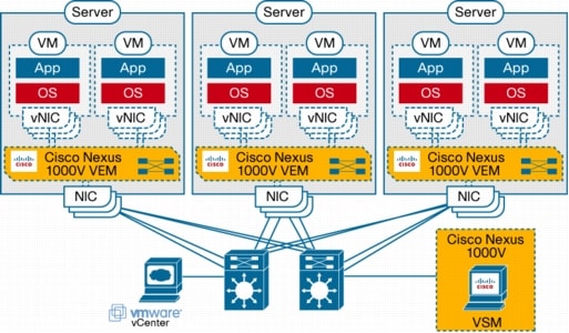
In the Cisco Nexus 1000V Series, traffic between virtual machines is switched locally at each instance of a VEM. Each VEM is also responsible for interconnecting the local virtual machines with the rest of the network through the upstream access-layer network switch (blade, top-of-rack, end-of-row, etc.). The VSM is responsible for running the control plane protocols and configuring the state of each VEM accordingly, but it never takes part in the actual forwarding of packets (Figure 3).
Figure 3. Cisco Nexus 1000V Series Distributed Switching Architecture
Deploying VN-Link with Network Interface Virtualization
In addition to the distributed virtual switch model, which requires a tight integration between the hypervisor, its management layer, and the virtual networking components and implements switching in software within the hypervisor, Cisco has developed a hardware approach based on the concept of network interface virtualization. NIV completely removes any switching function from the hypervisor and locates it in a hardware network switch physically independent of the server. NIV still requires a component on the host, called the interface virtualizer, that can be implemented either in software within the hypervisor or in hardware within an interface virtualizer-capable adapter. The purpose of the interface virtualizer is twofold:
• For traffic going from the server to the network, the interface virtualizer identifies the source vNIC and explicitly tags each of the packets generated by that vNIC with a unique tag, also known as a virtual network tag (VNTag).
• For traffic received from the network, the interface virtualizer removes the VNTag and directs the packet to the specified vNIC.
The interface virtualizer never performs any local switching between virtual machines. The switching process is completely decoupled from the hypervisor, which brings networking of virtual machines to feature parity with networking of physical devices.
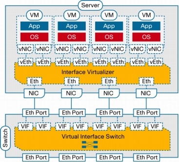
Switching is always performed by the network switch to which the interface virtualizer connects, which in this case is called the virtual interface switch (VIS) to indicate its capability not only to switch between physical ports, but also between virtual interfaces (VIFs) corresponding to vNICs that are remote from the switch. Said in a different way, each vNIC in a virtual machine will correspond to a VIF in the VIS, and any switching or policy enforcement function will be performed within the VIS and not in the hypervisor. The VIS can be any kind of access-layer switch in the network (a blade, top-of-rack, or end-of-row switch) as long as it supports NIV (Figure 4).
Figure 4. Architectural Elements of the NIV Model
An important consequence of the NIV model is that the VIS cannot be just any IEEE 802.1D-compliant Ethernet switch, but it must implement some extensions to support the newly defined satellite relationships. These extensions are link local and must be implemented both in the switch and in the interface virtualizer. Without such extensions, the portions of traffic belonging to different virtual machines cannot be identified because the virtual machines are multiplexed over a single physical link.
In addition, a VIS must be enabled to potentially forward a frame back on the same inbound port from which it was received. The IEEE 801.D standard that defines the operation of Layer 2 Ethernet switches clearly states that a compliant switch is never allowed to forward any frames back on the same interface from which they were received. This measure was originally introduced in the standard to avoid the creation of loops in Layer 2 topologies while enabling relatively simple hardware implementations of Layer 2 forwarding engines. The technology that is currently available for implementing forwarding engines allows much more sophisticated algorithms, and thus this requirement no longer needs to be imposed. Nonetheless, the capability of a network switch to send packets back on the same interface from which they were received still requires the proper level of standardization. Cisco defined a protocol, VNTag, that has been submitted to the IEEE 802.3 task force for standardization.
NIV represents innovation at Layer 2 that is designed for deployment within the VN-Link operating framework. Specifically, it includes the same mechanisms, such as port profiles, vEth interfaces, support for virtual machine mobility, a consistent network deployment and operating model, and integration with hypervisor managers, as the Cisco Nexus 1000V Series.
Conclusion
The introduction of bladed server architectures and server virtualization has invalidated several design, operational, and diagnostic assumptions of data center networks. Server virtualization allows multiple OS images to transparently share the same physical server and I/O devices. As a consequence, it introduces the need to support local switching between different Virtual Machines within the same server. Cisco and VMware have collaborated to define a set of APIs that enable transparent integration of third-party networking capabilities within the VMware Virtual Infrastructure.
Cisco has been the first networking vendor to take advantage of such capabilities to deliver VN-Link, a portfolio of networking solutions that can operate directly within the distributed hypervisor layer and offer a feature set and operational model that is familiar and consistent with other Cisco networking products. This approach provides an end-to-end network solution to the new requirements created by server virtualization.
VN-Link can be implemented as a Cisco distributed virtual switch, or DVS, running entirely in software within the hypervisor layer (Cisco Nexus 1000V Series) or in a new class of devices that support network interface virtualization, or NIV, and eliminate the need for software-based switching within hypervisors. VN-Link provides an immediate solution to virtual machine networking requirements, while laying the foundation for future enhanced and simplified connectivity options in virtualized data centers.
GD Star Rating
loading...
GD Star Rating
loading...
![]() Cisco and VMware have collaborated to address new challenges that have arisen from the introduction of bladed server architectures and subsequently of server virtualization. With Cisco VN-Link, you will find a portfolio of networking solutions that can operate directly within the distributed hypervisor layer and offer a feature set and operational model that is familiar and consistent with other Cisco networking products. This approach provides an end-to-end network solution to the new requirements created by server virtualization.
Cisco and VMware have collaborated to address new challenges that have arisen from the introduction of bladed server architectures and subsequently of server virtualization. With Cisco VN-Link, you will find a portfolio of networking solutions that can operate directly within the distributed hypervisor layer and offer a feature set and operational model that is familiar and consistent with other Cisco networking products. This approach provides an end-to-end network solution to the new requirements created by server virtualization.


